Japanese Joinery
Our design is based on the Japanese art of nail-free wood joinery, also known as Sashimono. Examples of this practice into modern day can be seen in Japanese toy puzzle boxes, furniture, and geometric sculptures. The idea behind this practice is to make aesthetic designs that will fit together perfectly, thus negating the need for nails or other joining materials. This is a simple, elegant solution to making furniture. We essentially wanted to make a piece of furniture that uses this kind of joint and will be able to carry a load. The experiment was then to see if a material such as PLA will fit together in a joinery like this, given the surface finish of the FDM printed parts. The design is to make a chair with several of these joints, that will fit together without any kind of adhesives or nails.
Design
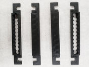
The chair consists of a total of 13 components: 4 legs, 1 front seat frame, 1 back seat frame, 2 pairs of side seat frames, 1 seat, and 2 back panels. The chair was designed in Solidworks using the joint in the image below. This joint made up the frame of the seat and the legs. The chair seat was designed as a merged series of rods. Unlike the front seat frame, the back seat frame has two bars extruded with two slots, through which thin rectangular boards will slide as supports for the back. Japanese joinery is therefore only used to assemble the bottom portion of the chair: joints between the seat frame, legs, and the back frame.

The seat frame on the sides needed to be created into two parts, so that the actual seat can be assembled and secured. The rest of the components were modeled as single parts. The holes on the back frame is extruded through entirely for one of the frames and only partially for the other. This is done so that the back boards do not slide loose, since it is unlikely that we are able to control the tolerances of the fit to the degree necessary to allow for the back boards to tightly fit into the holes.
The chair seat, made of bars running horizontally across the chair seat frame, was made to reduce the overall weight of the design and to increase aesthetics. It also allowed for the bars to slide into the chair seat frame, adding to the joinery inspiration of the chair itself. The full assembly of the chair is shown below.

Printing & Orientation
Most of the components are long, thin bars, and so, in order to effectively print the parts, we had to orient them vertically on the FDM printer. This would minimize warping, as only a small surface area is on the build platform, reducing lifting and delamination as well. This was also the only orientation that could be printed without needing supports for the overhangs that occurred from the joints.
Printing in this orientation, no supports were necessary and the parts printed with minimal warping or adhesion problems. Each part required only one iteration, though there were problems associated with the raft. To reduce the chance of lifting, we printed on a raft. However, the raft could not easily be removed from the part, and there was intensive post-processing to file away the raft, rather than peeling it off manually after the print was completed. This affected the stability and fit of the final design. The printed components and the finished assembly can be seen below.


